Background: Minecraft and Games as an Educational Tool
Throughout grade school, I have had the privilege to have experienced educational video games in school. Some of the earliest examples I could remember were Starfall, one I used when I was in elementary school, Lightbot, which was used to teach programming when I was in middle school, and more. I remember when the creators of Minecraft announced the Minecraft Education Edition. I remember seeing that it contained the periodic table of elements and you could combine elements together to create a variety of compounds or chemical reactions. They also offer a ton of lessons and tools to incorporate gaming into a variety of subjects.
I have incorporated Minecraft into my educational journey many times. In middle school, I took a course where we discussed the engineering design process. I applied every step of this process and documented each step to create a scaled replica of the Eifel Tower in Minecraft. I didn’t have the tools or resources to actually create something, especially coming from a low-income household where I didn’t always have the funds for crafts. Minecraft gave me the playground to create anything I wanted. I of course talked to my instructor for permission prior to starting the project and pitched my idea and how I was going to approach the assignment, so it didn’t seem like I was trying to come up with an excuse to play games in class.
In high school, my AP Physics teacher gave us the freedom to create anything physics related as one of our big projects for the course. I used this as an opportunity to once again incorporate Minecraft into my education and I calculated various gravity values in Minecraft. I say various because some items fall at different rates. I used my skills in content creation to edit the video and present it to my class. Many students were excited to see Minecraft and my work was (mostly) technically correct, so it was approved. I even had some of my friends help me with the project. We built various rollercoasters to be used for the video and it was so fun to work on.
Something I agree with, as well as many of the classmates I’ve had throughout the years, is that education and learning is best when it’s made fun. Having fun demonstrations, tools, assignments, and activities is what makes students want to learn. An example that immediately came into my head is how my World History teacher in high school had us learn how tough an assembly line was like during our unit on the industrial revolution by recreating one. She played an audio of loud machinery, made the room very gloomy and dark, and turned the heater on to recreate the experience of working in a factory. We were tasked to create paper dolls where each person had a specific task, like cut out the parts, coloring, pasting them together, etc. The class was split into two teams and whoever was able to “manufacture” the most dolls won. History was my least favorite subject, still is to this day, but I remember the most about history from her class, even years later. To Ms. Calzada, thank you for making education fun!
Introduction
This year for Pi Day (March 14th, or 3.14), I joined the Twitch Women’s Guild for a Pi Day Raid Train for the second year in a row. If you are unfamiliar with the term “raid train,” it’s a large live event involving a number of streamers where you stream for a certain time frame (typically about 1-4 hours) and then pass the viewers (which is referred to as “raiding” on Twitch) to another content creator in a chain. For this event, we had about 13 creators participate who are women in STEM. Last year, for my slot on the train, I hosted a workshop where we used the Python turtle library to create a turtle. You can find the tutorial here. This year, I decided to teach logic gates through Minecraft.
Logic Gates
Logic gates are a basic concept in programming and technology as a whole. Logic gates take in a number of inputs to produce a single output. For the examples in this demonstration, I used one or two inputs. Logic gates can be put together to create various combinations. Logic gates typically take binary (0 or 1) or Boolean (true or false) inputs. For this example, I explained them in both binary and Boolean inputs, but we simplified it to “ON” or “OFF” as we were using lamps in the game. Logic gates also have diagrams that are used to create visual representations for the gates. This helps to visually see how information flows, instead of looking at lines in code or digital circuits in electronics. We covered five different logic gates: I/O gate, NOT gate, AND gate, OR gate, and XOR gate.
Truth Tables
Truth tables are charts used to map the different combinations of inputs and what their outputs will look like. These tables have a column for every input and output and rows for every possible combination of inputs. You can find examples of the truth tables for each section below.
Input and Output (I/O) Gate
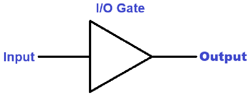
The I/O gate, also commonly referred to as Buffer, is the most simple logic gate. This is a gate takes the input as the output. Below is the truth table for this gate:
| Input | Output |
|---|---|
| OFF | OFF |
| ON | ON |
Below is the diagram symbol for an I/O gate. The diagram has one input, a triangle is the symbol for the I/O gate, and one output.
NOT Gate
The NOT gate is a logic gate that inverts the input to produce the opposite as the output. Below is the truth table for this gate:
| Input | Output |
|---|---|
| OFF | ON |
| ON | OFF |
Below is the diagram symbol for a NOT gate. The diagram has one input, a triangle with a circle on the end serves as the symbol for the NOT gate, and one output.

AND Gate
The AND gate is a logic gate with two inputs that produce an “ON” output only when both inputs are “ON.” Below is the truth table for this gate:
| Input 1 | Input 2 | Output |
|---|---|---|
| OFF | OFF | OFF |
| ON | OFF | OFF |
| OFF | ON | OFF |
| ON | ON | ON |
Below is the diagram symbol for an AND gate. The diagram has two inputs, a semicircle with a long body as the symbol for the AND gate, and one output.

OR Gate
The OR gate is a logic gate with two inputs that produce an “ON” output when one or both of the inputs are “ON.” Below is the truth table for this gate:
| Input 1 | Input 2 | Output |
|---|---|---|
| OFF | OFF | OFF |
| ON | OFF | ON |
| OFF | ON | ON |
| ON | ON | ON |
Below is the diagram symbol for an OR gate. The diagram has two inputs, a semicircle with a curved end as the symbol for the OR gate, and one output.

XOR Gate
The XOR gate is a logic gate with two inputs that produce an “ON” output when, and only when, one of the inputs is “ON.” Below is the truth table for this gate:
| Input 1 | Input 2 | Output |
|---|---|---|
| OFF | OFF | OFF |
| ON | OFF | ON |
| OFF | ON | ON |
| ON | ON | OFF |
Below is the diagram symbol for an XOR gate. The diagram has two inputs, a semicircle with a curved end and a curved line before it as the symbol for the XOR gate, and one output.

Setting Up Minecraft
To make the demonstration more immersive and fun, I decided to follow this tutorial to build a steampunk-styled factory. My building style in Minecraft isn’t as fancy or advanced as some of the YouTube builders, so following a tutorial was my best option. I excluded the interior furniture from the build, as I needed the open area to place the circuits. I then surrounded the area in extra-large spruce trees, created a river, and made a path by placing a variety of blocks in a random pattern to give it a nice scene.

The factory itself has 3 levels. I decided to make each level more difficult than the last, but found that the second level was a little more complex than the third, so I recommend to swap these two levels if you’re planning on using this as a lesson plan. Otherwise, you can keep it as-is and just make a note.
Materials
You will need the following items from Minecraft:
- Levers
- These will serve as our inputs. When levers are facing up, they are in an “OFF” position. When they are interacted with and face down, they are in an “ON” position.
- Redstone Dust
- Redstone dust is what connects items together to pass a current. We are going to use it to connect the circuits together.
- Redstone Torches
- Here, we’re using Redstone Torches to invert signals to create our logic gates. I will explain how to do this later on.
- Redstone Lamps
- Redstone Lamps take the output signal from our circuits to either turn on or off. This will give a clearer visual for the output.
- Any type of Block
- The blocks will be used to make the logic gates work, as some of the items need to be placed on or above a block to work. Ideally, you want to use the same block for every circuit to make it easier to understand.
- Additionally, if you’re using the tutorial for the factory building, you’ll notice there’s a lot of glass blocks and trap doors on the 3rd level. You cannot place Redstone dust on these items, so you will need the blocks to create a path where the Redstone can be placed on to avoid any issues. I’ll explain this in depth later.

Level 1: Introduction to Logic Gates
The first floor has a smaller area to the right that I used for our single input gates, the I/O and NOT gates. Since these are single input gates, you don’t need a lot of space to build these. Below are how I built them and what you’ll need to do the same.
I/O Gate Using Redstone
For the I/O gate, you will need:
- 1 Lever – our input
- 1 of any block – the logic gate
- 1 Redstone – the output
- 1 Redstone Lamp – the visual for our output
This can also be done without the block by simply putting the lever on the lamp or next to the Redstone dust trail. Given that the rest of the circuits use the block, I wanted to keep everything uniform to better follow along. You may also notice while interacting with the circuit that the Redstone turns a bright red color when powered. This is because Redstone dust alone is a power output. We use the output from the Redstone dust to power items, such as pistons and dispensers, but we won’t be using these in any of our examples. Instead, we use the Redstone lamp.

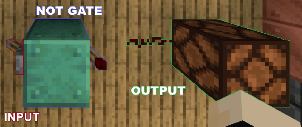
NOT Gate Using Redstone
For the NOT gate, you will need:
- 1 Lever – the input
- 1 of any block – the logic gate
- 1 Redstone Torch – the second part to the logic gate
- 1 Redstone – the output
- 1 Redstone Lamp- the visual for our output
As I mentioned earlier, Redstone torches can act as an inverter. This is because Redstone torches are already a power source. When you place a Redstone Torch next to a Redstone Lamp, it will power the lamp on. So when we put a Redstone Torch on a block with a lever on the other side, the block emits an “ON” signal when the lever is “OFF,” giving us a NOT gate. Pretty cool right?
The next section is the large area on the first floor.
AND Gate Using Redstone
For the AND gate, you will need:
- 2 Levers – the 2 inputs for the gate
- 3 of any block – the gate
- 3 Redstone Torches – the second part of the gate
- 2 Redstone – 1 will be used for the gate, 1 for the output
- 1 Redstone Lamp – the visual for our output
Going back to the torches being used as inverters, The torch on the top of the block react to the signal given from the levers. When a lever is “ON,” the torch turns off. There is also another torch on the side of the block in between the signals. This torch gets the signal from the Redstone dust between both torches. The Redstone dust takes in the input from both torches. When one or both torches are lit, the Redstone dust remains on. This then inverts the signal from the torch in the middle. To get the output to be “ON,” we need the two torches on the top to be “OFF” (which happens by both inputs being “ON”). This will create an “OFF” signal for the Redstone Dust, keeping the middle torch “ON” and producing an “ON” signal for the output, ultimately lighting up the Redstone Lamp. The way Minecraft does it is a little bit complex, so I just explain it as a whole system instead of each individual item.

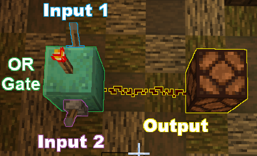
OR Gate Using Redstone
For the OR gate, you will need:
- 2 Levers – the 2 inputs for the gate
- 1 of any block – the gate
- 1 Redstone Torch – the second part of the gate
- 1 Redstone – the output (the image uses two, I just didn’t want the circuit to look too crowded so I made it longer, but 1 is fine)
- 1 Redstone Lamp – the visual for our output
The Redstone torch inverts the signal from the levers. When one of the levers turns “ON,” the torch turns “OFF” and the Redstone dust takes in the signal from the levers. The reason for this is because the torch is on top of the block, so it can’t reach the dust on the floor. This creates an OR gate since either one of the levers can create the ON output, including both levers.
XOR Gate Using Redstone
For the XOR Gate, you will need:
- 2 Levers – the 2 inputs for the gate
- 6 of any block – the gate
- 7 Redstone Torches – the second and third part of the gate
- 8 Redstone – 7 used for the gate, 1 used for the output
- 1 Redstone Lamp – the visual for our output
The XOR gate is the most complicated gate in the group. It starts off setting up an AND Gate. The last group of torches produce an “OFF” output when both of the levers are pulled, because when both torches are on, they invert each other’s signal. When only one is on, it continues. The other stages don’t use this gate because of its complexity, but you can build your own circuit using this gate.

Next, we’re going to do our first exercise with the logic gates. I have combined various logic gates into one circuit. This will let us experiment with different inputs to produce an “ON” output. I’ll cover how to make complex truth tables to map overall inputs by breaking the pieces of the circuit down.

Level 2: Combining Logic Gates
Below is an image of the circuit I have created. I’ll be breaking up the process for this circuit into steps. The third level will be a complete solo exercise with a different circuit. Let’s jump in!

Step 1: Identifying the gates
Our very first step is to identify the different gates on the circuit. Take a look at the building blocks we have in Level 1 and try to see which parts look identical. You should have something that looks like this:

Some of this might be tricky. We’re used to the blocks having a lever attached to them to serve as inputs. Instead, we’re using the outputs from the gates as the inputs for the next gates. If you recall, I mentioned that the Redstone dust at the end of the gate serves as the output. We extend the Redstone dust to reach the next gates in this example. Additionally, one of the OR gates looks funny right? It’s taking the output from an AND gate and another OR gate and meeting in the middle to produce a single output. Before, it would use the signal from both of the levers on the sides. This is doing the same thing, except using the Redstone output.
Now, trying to trace all of the inputs and outputs can get confusing, so the next step is to identify these!
Step 2: Identifying Inputs and Outputs
To start, we’re going to number each lever as inputs. This should look like the following:

As you can see, there are 6 levers providing an input at the start of the circuit. Each logic gate produces one output. Since we have 3 gates at the start, this produces 3 outputs which get turned into inputs for the next layer of gates. We give them a new input name. See below for an example:
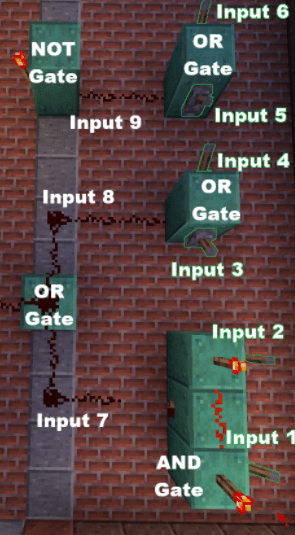
Now, you can also think of it as outputs. For example, Input 7 is the Output of Inputs 1 and 2. You can write it as “Output 1+2.” I’m just numbering it to better track them on the Truth Tables later.
Now, we move to the last gate.
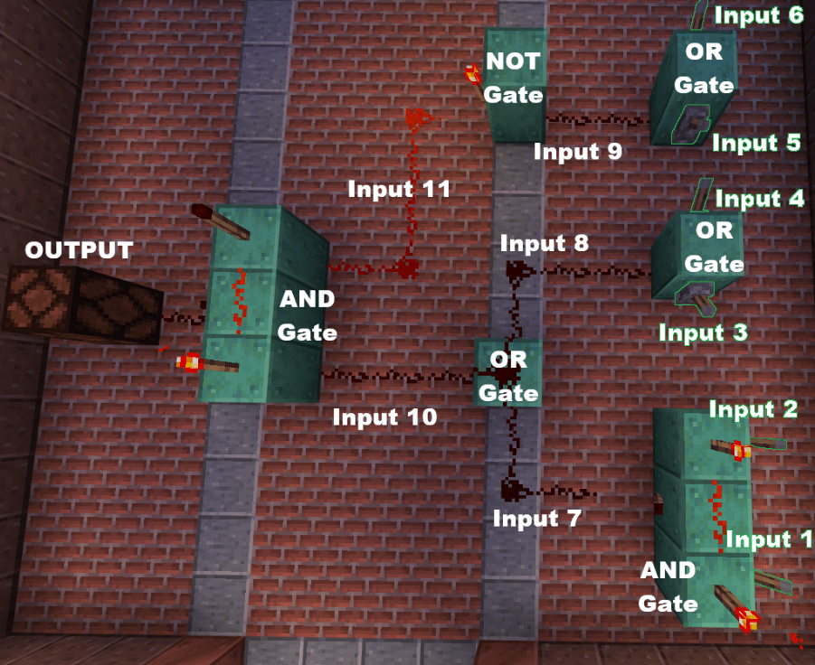
Input 10 is the Output of 7 and 8 and Input 11 is the Output of Input 9. Since Input 9 goes into a NOT Gate, it only needs one Input where it’s inverted to produce Input 11.
Finally, we have a single Output which has already been labeled at the start. This is where our Redstone Lamp is. Next, we’re going to create a diagram using the symbols we covered at the beginning.
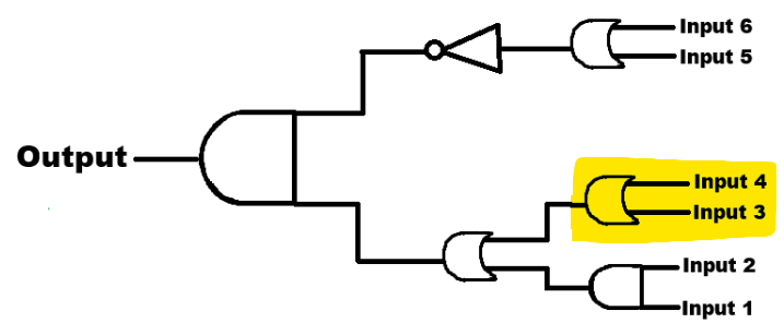
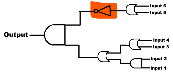
Step 3: Creating a Diagram
Since we already identified the gates and the inputs, we can create a diagram. Typically, diagrams go from the left to right, but I realized that I took the screenshots backwards (oops), so we’ll be making it from right to left.

As you can see from the diagram above, we have our 6 lever inputs on the right, followed by 3 gates (1 AND and 2 OR gates). These then produce a single output which gets inputted to 2 other gates (1 NOT and 1 OR). These 2 gates produce a single output which goes into a final AND gate to produce the overall output. You can follow the lines in the diagram to see how each input leads to the output. This is a much easier way to trace inputs. The Redstone blocks make it slightly difficult to visualize at times, so it’s best to make a diagram. Next, we’re going to create a truth table based on this diagram.
Step 4: Creating a Truth Table
To start, I recommend marking every possible combination for the lever inputs. The way to calculate how many inputs combinations you have is as follows:
Combinations = 2n
Where “n” is the number of inputs. Because our inputs are binary (having two possible options), we use 2n. If the inputs could only be integers from 0 to 9, we would use 10n.
So, since we have 6 inputs, Combinations = 26=64. That’s a lot right? The good news is that we have tools to do this for us. I used ChatGPT to produce all of the possible inputs for me. I gave it the following prompt:
I have 6 binary inputs. Can you give me a list of all of the combinations, numbered, where the inputs are either “ON” or “OFF”?
I went ahead and made the table for you below:
| # | Input 1 | Input 2 | Input 3 | Input 4 | Input 5 | Input 6 |
|---|---|---|---|---|---|---|
| 1 | OFF | OFF | OFF | OFF | OFF | OFF |
| 2 | OFF | OFF | OFF | OFF | OFF | ON |
| 3 | OFF | OFF | OFF | OFF | ON | OFF |
| 4 | OFF | OFF | OFF | OFF | ON | ON |
| 5 | OFF | OFF | OFF | ON | OFF | OFF |
| 6 | OFF | OFF | OFF | ON | OFF | ON |
| 7 | OFF | OFF | OFF | ON | ON | OFF |
| 8 | OFF | OFF | OFF | ON | ON | ON |
| 9 | OFF | OFF | ON | OFF | OFF | OFF |
| 10 | OFF | OFF | ON | OFF | OFF | ON |
| 11 | OFF | OFF | ON | OFF | ON | OFF |
| 12 | OFF | OFF | ON | OFF | ON | ON |
| 13 | OFF | OFF | ON | ON | OFF | OFF |
| 14 | OFF | OFF | ON | ON | OFF | ON |
| 15 | OFF | OFF | ON | ON | ON | OFF |
| 16 | OFF | OFF | ON | ON | ON | ON |
| 17 | OFF | ON | OFF | OFF | OFF | OFF |
| 18 | OFF | ON | OFF | OFF | OFF | ON |
| 19 | OFF | ON | OFF | OFF | ON | OFF |
| 20 | OFF | ON | OFF | OFF | ON | ON |
| 21 | OFF | ON | OFF | ON | OFF | OFF |
| 22 | OFF | ON | OFF | ON | OFF | ON |
| 23 | OFF | ON | OFF | ON | ON | OFF |
| 24 | OFF | ON | OFF | ON | ON | ON |
| 25 | OFF | ON | ON | OFF | OFF | OFF |
| 26 | OFF | ON | ON | OFF | OFF | ON |
| 27 | OFF | ON | ON | OFF | ON | OFF |
| 28 | OFF | ON | ON | OFF | ON | ON |
| 29 | OFF | ON | ON | ON | OFF | OFF |
| 30 | OFF | ON | ON | ON | OFF | ON |
| 31 | OFF | ON | ON | ON | ON | OFF |
| 32 | OFF | ON | ON | ON | ON | ON |
| 33 | ON | OFF | OFF | OFF | OFF | OFF |
| 34 | ON | OFF | OFF | OFF | OFF | ON |
| 35 | ON | OFF | OFF | OFF | ON | OFF |
| 36 | ON | OFF | OFF | OFF | ON | ON |
| 37 | ON | OFF | OFF | ON | OFF | OFF |
| 38 | ON | OFF | OFF | ON | OFF | ON |
| 39 | ON | OFF | OFF | ON | ON | OFF |
| 40 | ON | OFF | OFF | ON | ON | ON |
| 41 | ON | OFF | ON | OFF | OFF | OFF |
| 42 | ON | OFF | ON | OFF | OFF | ON |
| 43 | ON | OFF | ON | OFF | ON | OFF |
| 44 | ON | OFF | ON | OFF | ON | ON |
| 45 | ON | OFF | ON | ON | OFF | OFF |
| 46 | ON | OFF | ON | ON | OFF | ON |
| 47 | ON | OFF | ON | ON | ON | OFF |
| 48 | ON | OFF | ON | ON | ON | ON |
| 49 | ON | ON | OFF | OFF | OFF | OFF |
| 50 | ON | ON | OFF | OFF | OFF | ON |
| 51 | ON | ON | OFF | OFF | ON | OFF |
| 52 | ON | ON | OFF | OFF | ON | ON |
| 53 | ON | ON | OFF | ON | OFF | OFF |
| 54 | ON | ON | OFF | ON | OFF | ON |
| 55 | ON | ON | OFF | ON | ON | OFF |
| 56 | ON | ON | OFF | ON | ON | ON |
| 57 | ON | ON | ON | OFF | OFF | OFF |
| 58 | ON | ON | ON | OFF | OFF | ON |
| 59 | ON | ON | ON | OFF | ON | OFF |
| 60 | ON | ON | ON | OFF | ON | ON |
| 61 | ON | ON | ON | ON | OFF | OFF |
| 62 | ON | ON | ON | ON | OFF | ON |
| 63 | ON | ON | ON | ON | ON | OFF |
| 64 | ON | ON | ON | ON | ON | ON |
Now that we have all of our combinations, we add a column for each logic gate. Let’s start with the first AND gate. Input 1 AND Input 2 creates an output which we renamed as Input 7. Now, although the table shows all 6 inputs, we’re only going to be using Inputs 1 and 2. Recall that an AND gate produces an “ON” output only when both inputs are ON.
Since the table shows all of the possible combinations, we have some duplicates for the first gate. Because the table has a pattern, just fill the “ON” outputs first and the rest you can auto fill as “OFF”

You should end up with something like this:
| # | Input 1 | Input 2 | Input 3 | Input 4 | Input 5 | Input 6 | Input 7: 1 AND 2 |
|---|---|---|---|---|---|---|---|
| 1 | OFF | OFF | OFF | OFF | OFF | OFF | OFF |
| 2 | OFF | OFF | OFF | OFF | OFF | ON | OFF |
| 3 | OFF | OFF | OFF | OFF | ON | OFF | OFF |
| 4 | OFF | OFF | OFF | OFF | ON | ON | OFF |
| 5 | OFF | OFF | OFF | ON | OFF | OFF | OFF |
| 6 | OFF | OFF | OFF | ON | OFF | ON | OFF |
| 7 | OFF | OFF | OFF | ON | ON | OFF | OFF |
| 8 | OFF | OFF | OFF | ON | ON | ON | OFF |
| 9 | OFF | OFF | ON | OFF | OFF | OFF | OFF |
| 10 | OFF | OFF | ON | OFF | OFF | ON | OFF |
| 11 | OFF | OFF | ON | OFF | ON | OFF | OFF |
| 12 | OFF | OFF | ON | OFF | ON | ON | OFF |
| 13 | OFF | OFF | ON | ON | OFF | OFF | OFF |
| 14 | OFF | OFF | ON | ON | OFF | ON | OFF |
| 15 | OFF | OFF | ON | ON | ON | OFF | OFF |
| 16 | OFF | OFF | ON | ON | ON | ON | OFF |
| 17 | OFF | ON | OFF | OFF | OFF | OFF | OFF |
| 18 | OFF | ON | OFF | OFF | OFF | ON | OFF |
| 19 | OFF | ON | OFF | OFF | ON | OFF | OFF |
| 20 | OFF | ON | OFF | OFF | ON | ON | OFF |
| 21 | OFF | ON | OFF | ON | OFF | OFF | OFF |
| 22 | OFF | ON | OFF | ON | OFF | ON | OFF |
| 23 | OFF | ON | OFF | ON | ON | OFF | OFF |
| 24 | OFF | ON | OFF | ON | ON | ON | OFF |
| 25 | OFF | ON | ON | OFF | OFF | OFF | OFF |
| 26 | OFF | ON | ON | OFF | OFF | ON | OFF |
| 27 | OFF | ON | ON | OFF | ON | OFF | OFF |
| 28 | OFF | ON | ON | OFF | ON | ON | OFF |
| 29 | OFF | ON | ON | ON | OFF | OFF | OFF |
| 30 | OFF | ON | ON | ON | OFF | ON | OFF |
| 31 | OFF | ON | ON | ON | ON | OFF | OFF |
| 32 | OFF | ON | ON | ON | ON | ON | OFF |
| 33 | ON | OFF | OFF | OFF | OFF | OFF | OFF |
| 34 | ON | OFF | OFF | OFF | OFF | ON | OFF |
| 35 | ON | OFF | OFF | OFF | ON | OFF | OFF |
| 36 | ON | OFF | OFF | OFF | ON | ON | OFF |
| 37 | ON | OFF | OFF | ON | OFF | OFF | OFF |
| 38 | ON | OFF | OFF | ON | OFF | ON | OFF |
| 39 | ON | OFF | OFF | ON | ON | OFF | OFF |
| 40 | ON | OFF | OFF | ON | ON | ON | OFF |
| 41 | ON | OFF | ON | OFF | OFF | OFF | OFF |
| 42 | ON | OFF | ON | OFF | OFF | ON | OFF |
| 43 | ON | OFF | ON | OFF | ON | OFF | OFF |
| 44 | ON | OFF | ON | OFF | ON | ON | OFF |
| 45 | ON | OFF | ON | ON | OFF | OFF | OFF |
| 46 | ON | OFF | ON | ON | OFF | ON | OFF |
| 47 | ON | OFF | ON | ON | ON | OFF | OFF |
| 48 | ON | OFF | ON | ON | ON | ON | OFF |
| 49 | ON | ON | OFF | OFF | OFF | OFF | ON |
| 50 | ON | ON | OFF | OFF | OFF | ON | ON |
| 51 | ON | ON | OFF | OFF | ON | OFF | ON |
| 52 | ON | ON | OFF | OFF | ON | ON | ON |
| 53 | ON | ON | OFF | ON | OFF | OFF | ON |
| 54 | ON | ON | OFF | ON | OFF | ON | ON |
| 55 | ON | ON | OFF | ON | ON | OFF | ON |
| 56 | ON | ON | OFF | ON | ON | ON | ON |
| 57 | ON | ON | ON | OFF | OFF | OFF | ON |
| 58 | ON | ON | ON | OFF | OFF | ON | ON |
| 59 | ON | ON | ON | OFF | ON | OFF | ON |
| 60 | ON | ON | ON | OFF | ON | ON | ON |
| 61 | ON | ON | ON | ON | OFF | OFF | ON |
| 62 | ON | ON | ON | ON | OFF | ON | ON |
| 63 | ON | ON | ON | ON | ON | OFF | ON |
| 64 | ON | ON | ON | ON | ON | ON | ON |
Now, make another column for the second gate. This is the OR gate for inputs 3 and 4. They produce an output that we renamed as Input 8. Recall that an OR gate produces an “ON” input when any input or both input is “ON.” The only time it produces an “OFF” output is when both inputs are “OFF.”
You should end up with something like this:
| # | Input 1 | Input 2 | Input 3 | Input 4 | Input 5 | Input 6 | Input 7: 1 AND 2 | Input 8: 3 OR 4 |
|---|---|---|---|---|---|---|---|---|
| 1 | OFF | OFF | OFF | OFF | OFF | OFF | OFF | OFF |
| 2 | OFF | OFF | OFF | OFF | OFF | ON | OFF | OFF |
| 3 | OFF | OFF | OFF | OFF | ON | OFF | OFF | OFF |
| 4 | OFF | OFF | OFF | OFF | ON | ON | OFF | OFF |
| 5 | OFF | OFF | OFF | ON | OFF | OFF | OFF | ON |
| 6 | OFF | OFF | OFF | ON | OFF | ON | OFF | ON |
| 7 | OFF | OFF | OFF | ON | ON | OFF | OFF | ON |
| 8 | OFF | OFF | OFF | ON | ON | ON | OFF | ON |
| 9 | OFF | OFF | ON | OFF | OFF | OFF | OFF | ON |
| 10 | OFF | OFF | ON | OFF | OFF | ON | OFF | ON |
| 11 | OFF | OFF | ON | OFF | ON | OFF | OFF | ON |
| 12 | OFF | OFF | ON | OFF | ON | ON | OFF | ON |
| 13 | OFF | OFF | ON | ON | OFF | OFF | OFF | ON |
| 14 | OFF | OFF | ON | ON | OFF | ON | OFF | ON |
| 15 | OFF | OFF | ON | ON | ON | OFF | OFF | ON |
| 16 | OFF | OFF | ON | ON | ON | ON | OFF | ON |
| 17 | OFF | ON | OFF | OFF | OFF | OFF | OFF | OFF |
| 18 | OFF | ON | OFF | OFF | OFF | ON | OFF | OFF |
| 19 | OFF | ON | OFF | OFF | ON | OFF | OFF | OFF |
| 20 | OFF | ON | OFF | OFF | ON | ON | OFF | OFF |
| 21 | OFF | ON | OFF | ON | OFF | OFF | OFF | ON |
| 22 | OFF | ON | OFF | ON | OFF | ON | OFF | ON |
| 23 | OFF | ON | OFF | ON | ON | OFF | OFF | ON |
| 24 | OFF | ON | OFF | ON | ON | ON | OFF | ON |
| 25 | OFF | ON | ON | OFF | OFF | OFF | OFF | ON |
| 26 | OFF | ON | ON | OFF | OFF | ON | OFF | ON |
| 27 | OFF | ON | ON | OFF | ON | OFF | OFF | ON |
| 28 | OFF | ON | ON | OFF | ON | ON | OFF | ON |
| 29 | OFF | ON | ON | ON | OFF | OFF | OFF | ON |
| 30 | OFF | ON | ON | ON | OFF | ON | OFF | ON |
| 31 | OFF | ON | ON | ON | ON | OFF | OFF | ON |
| 32 | OFF | ON | ON | ON | ON | ON | OFF | ON |
| 33 | ON | OFF | OFF | OFF | OFF | OFF | OFF | OFF |
| 34 | ON | OFF | OFF | OFF | OFF | ON | OFF | OFF |
| 35 | ON | OFF | OFF | OFF | ON | OFF | OFF | OFF |
| 36 | ON | OFF | OFF | OFF | ON | ON | OFF | OFF |
| 37 | ON | OFF | OFF | ON | OFF | OFF | OFF | ON |
| 38 | ON | OFF | OFF | ON | OFF | ON | OFF | ON |
| 39 | ON | OFF | OFF | ON | ON | OFF | OFF | ON |
| 40 | ON | OFF | OFF | ON | ON | ON | OFF | ON |
| 41 | ON | OFF | ON | OFF | OFF | OFF | OFF | ON |
| 42 | ON | OFF | ON | OFF | OFF | ON | OFF | ON |
| 43 | ON | OFF | ON | OFF | ON | OFF | OFF | ON |
| 44 | ON | OFF | ON | OFF | ON | ON | OFF | ON |
| 45 | ON | OFF | ON | ON | OFF | OFF | OFF | ON |
| 46 | ON | OFF | ON | ON | OFF | ON | OFF | ON |
| 47 | ON | OFF | ON | ON | ON | OFF | OFF | ON |
| 48 | ON | OFF | ON | ON | ON | ON | OFF | ON |
| 49 | ON | ON | OFF | OFF | OFF | OFF | ON | OFF |
| 50 | ON | ON | OFF | OFF | OFF | ON | ON | OFF |
| 51 | ON | ON | OFF | OFF | ON | OFF | ON | OFF |
| 52 | ON | ON | OFF | OFF | ON | ON | ON | OFF |
| 53 | ON | ON | OFF | ON | OFF | OFF | ON | ON |
| 54 | ON | ON | OFF | ON | OFF | ON | ON | ON |
| 55 | ON | ON | OFF | ON | ON | OFF | ON | ON |
| 56 | ON | ON | OFF | ON | ON | ON | ON | ON |
| 57 | ON | ON | ON | OFF | OFF | OFF | ON | ON |
| 58 | ON | ON | ON | OFF | OFF | ON | ON | ON |
| 59 | ON | ON | ON | OFF | ON | OFF | ON | ON |
| 60 | ON | ON | ON | OFF | ON | ON | ON | ON |
| 61 | ON | ON | ON | ON | OFF | OFF | ON | ON |
| 62 | ON | ON | ON | ON | OFF | ON | ON | ON |
| 63 | ON | ON | ON | ON | ON | OFF | ON | ON |
| 64 | ON | ON | ON | ON | ON | ON | ON | ON |
Now we make another column for the last gate in the first layer. This is an OR gate for inputs 5 and 6. It produces an output which we renamed as Input 9.

You should end up with the following:
| # | Input 1 | Input 2 | Input 3 | Input 4 | Input 5 | Input 6 | Input 7: 1 AND 2 | Input 8: 3 OR 4 | Input 9: 5 OR 6 |
|---|---|---|---|---|---|---|---|---|---|
| 1 | OFF | OFF | OFF | OFF | OFF | OFF | OFF | OFF | OFF |
| 2 | OFF | OFF | OFF | OFF | OFF | ON | OFF | OFF | ON |
| 3 | OFF | OFF | OFF | OFF | ON | OFF | OFF | OFF | ON |
| 4 | OFF | OFF | OFF | OFF | ON | ON | OFF | OFF | ON |
| 5 | OFF | OFF | OFF | ON | OFF | OFF | OFF | ON | OFF |
| 6 | OFF | OFF | OFF | ON | OFF | ON | OFF | ON | ON |
| 7 | OFF | OFF | OFF | ON | ON | OFF | OFF | ON | ON |
| 8 | OFF | OFF | OFF | ON | ON | ON | OFF | ON | ON |
| 9 | OFF | OFF | ON | OFF | OFF | OFF | OFF | ON | OFF |
| 10 | OFF | OFF | ON | OFF | OFF | ON | OFF | ON | ON |
| 11 | OFF | OFF | ON | OFF | ON | OFF | OFF | ON | ON |
| 12 | OFF | OFF | ON | OFF | ON | ON | OFF | ON | ON |
| 13 | OFF | OFF | ON | ON | OFF | OFF | OFF | ON | OFF |
| 14 | OFF | OFF | ON | ON | OFF | ON | OFF | ON | ON |
| 15 | OFF | OFF | ON | ON | ON | OFF | OFF | ON | ON |
| 16 | OFF | OFF | ON | ON | ON | ON | OFF | ON | ON |
| 17 | OFF | ON | OFF | OFF | OFF | OFF | OFF | OFF | OFF |
| 18 | OFF | ON | OFF | OFF | OFF | ON | OFF | OFF | ON |
| 19 | OFF | ON | OFF | OFF | ON | OFF | OFF | OFF | ON |
| 20 | OFF | ON | OFF | OFF | ON | ON | OFF | OFF | ON |
| 21 | OFF | ON | OFF | ON | OFF | OFF | OFF | ON | OFF |
| 22 | OFF | ON | OFF | ON | OFF | ON | OFF | ON | ON |
| 23 | OFF | ON | OFF | ON | ON | OFF | OFF | ON | ON |
| 24 | OFF | ON | OFF | ON | ON | ON | OFF | ON | ON |
| 25 | OFF | ON | ON | OFF | OFF | OFF | OFF | ON | OFF |
| 26 | OFF | ON | ON | OFF | OFF | ON | OFF | ON | ON |
| 27 | OFF | ON | ON | OFF | ON | OFF | OFF | ON | ON |
| 28 | OFF | ON | ON | OFF | ON | ON | OFF | ON | ON |
| 29 | OFF | ON | ON | ON | OFF | OFF | OFF | ON | OFF |
| 30 | OFF | ON | ON | ON | OFF | ON | OFF | ON | ON |
| 31 | OFF | ON | ON | ON | ON | OFF | OFF | ON | ON |
| 32 | OFF | ON | ON | ON | ON | ON | OFF | ON | ON |
| 33 | ON | OFF | OFF | OFF | OFF | OFF | OFF | OFF | OFF |
| 34 | ON | OFF | OFF | OFF | OFF | ON | OFF | OFF | ON |
| 35 | ON | OFF | OFF | OFF | ON | OFF | OFF | OFF | ON |
| 36 | ON | OFF | OFF | OFF | ON | ON | OFF | OFF | ON |
| 37 | ON | OFF | OFF | ON | OFF | OFF | OFF | ON | OFF |
| 38 | ON | OFF | OFF | ON | OFF | ON | OFF | ON | ON |
| 39 | ON | OFF | OFF | ON | ON | OFF | OFF | ON | ON |
| 40 | ON | OFF | OFF | ON | ON | ON | OFF | ON | ON |
| 41 | ON | OFF | ON | OFF | OFF | OFF | OFF | ON | OFF |
| 42 | ON | OFF | ON | OFF | OFF | ON | OFF | ON | ON |
| 43 | ON | OFF | ON | OFF | ON | OFF | OFF | ON | ON |
| 44 | ON | OFF | ON | OFF | ON | ON | OFF | ON | ON |
| 45 | ON | OFF | ON | ON | OFF | OFF | OFF | ON | OFF |
| 46 | ON | OFF | ON | ON | OFF | ON | OFF | ON | ON |
| 47 | ON | OFF | ON | ON | ON | OFF | OFF | ON | ON |
| 48 | ON | OFF | ON | ON | ON | ON | OFF | ON | ON |
| 49 | ON | ON | OFF | OFF | OFF | OFF | ON | OFF | OFF |
| 50 | ON | ON | OFF | OFF | OFF | ON | ON | OFF | ON |
| 51 | ON | ON | OFF | OFF | ON | OFF | ON | OFF | ON |
| 52 | ON | ON | OFF | OFF | ON | ON | ON | OFF | ON |
| 53 | ON | ON | OFF | ON | OFF | OFF | ON | ON | OFF |
| 54 | ON | ON | OFF | ON | OFF | ON | ON | ON | ON |
| 55 | ON | ON | OFF | ON | ON | OFF | ON | ON | ON |
| 56 | ON | ON | OFF | ON | ON | ON | ON | ON | ON |
| 57 | ON | ON | ON | OFF | OFF | OFF | ON | ON | OFF |
| 58 | ON | ON | ON | OFF | OFF | ON | ON | ON | ON |
| 59 | ON | ON | ON | OFF | ON | OFF | ON | ON | ON |
| 60 | ON | ON | ON | OFF | ON | ON | ON | ON | ON |
| 61 | ON | ON | ON | ON | OFF | OFF | ON | ON | OFF |
| 62 | ON | ON | ON | ON | OFF | ON | ON | ON | ON |
| 63 | ON | ON | ON | ON | ON | OFF | ON | ON | ON |
| 64 | ON | ON | ON | ON | ON | ON | ON | ON | ON |
Now, move on to the second layer. There is an OR gate that takes inputs 7 and 8. Input 7 is the output of inputs 1 and 2 and input 8 is the output of inputs 3 and 4. This creates a single output which has been renamed to Input 10.

You should have something that looks like this:
| # | Input 1 | Input 2 | Input 3 | Input 4 | Input 5 | Input 6 | Input 7: 1 AND 2 | Input 8: 3 OR 4 | Input 9: 5 OR 6 | Input 10: 7 OR 8 |
|---|---|---|---|---|---|---|---|---|---|---|
| 1 | OFF | OFF | OFF | OFF | OFF | OFF | OFF | OFF | OFF | OFF |
| 2 | OFF | OFF | OFF | OFF | OFF | ON | OFF | OFF | ON | OFF |
| 3 | OFF | OFF | OFF | OFF | ON | OFF | OFF | OFF | ON | OFF |
| 4 | OFF | OFF | OFF | OFF | ON | ON | OFF | OFF | ON | OFF |
| 5 | OFF | OFF | OFF | ON | OFF | OFF | OFF | ON | OFF | ON |
| 6 | OFF | OFF | OFF | ON | OFF | ON | OFF | ON | ON | ON |
| 7 | OFF | OFF | OFF | ON | ON | OFF | OFF | ON | ON | ON |
| 8 | OFF | OFF | OFF | ON | ON | ON | OFF | ON | ON | ON |
| 9 | OFF | OFF | ON | OFF | OFF | OFF | OFF | ON | OFF | ON |
| 10 | OFF | OFF | ON | OFF | OFF | ON | OFF | ON | ON | ON |
| 11 | OFF | OFF | ON | OFF | ON | OFF | OFF | ON | ON | ON |
| 12 | OFF | OFF | ON | OFF | ON | ON | OFF | ON | ON | ON |
| 13 | OFF | OFF | ON | ON | OFF | OFF | OFF | ON | OFF | ON |
| 14 | OFF | OFF | ON | ON | OFF | ON | OFF | ON | ON | ON |
| 15 | OFF | OFF | ON | ON | ON | OFF | OFF | ON | ON | ON |
| 16 | OFF | OFF | ON | ON | ON | ON | OFF | ON | ON | ON |
| 17 | OFF | ON | OFF | OFF | OFF | OFF | OFF | OFF | OFF | OFF |
| 18 | OFF | ON | OFF | OFF | OFF | ON | OFF | OFF | ON | OFF |
| 19 | OFF | ON | OFF | OFF | ON | OFF | OFF | OFF | ON | OFF |
| 20 | OFF | ON | OFF | OFF | ON | ON | OFF | OFF | ON | OFF |
| 21 | OFF | ON | OFF | ON | OFF | OFF | OFF | ON | OFF | ON |
| 22 | OFF | ON | OFF | ON | OFF | ON | OFF | ON | ON | ON |
| 23 | OFF | ON | OFF | ON | ON | OFF | OFF | ON | ON | ON |
| 24 | OFF | ON | OFF | ON | ON | ON | OFF | ON | ON | ON |
| 25 | OFF | ON | ON | OFF | OFF | OFF | OFF | ON | OFF | ON |
| 26 | OFF | ON | ON | OFF | OFF | ON | OFF | ON | ON | ON |
| 27 | OFF | ON | ON | OFF | ON | OFF | OFF | ON | ON | ON |
| 28 | OFF | ON | ON | OFF | ON | ON | OFF | ON | ON | ON |
| 29 | OFF | ON | ON | ON | OFF | OFF | OFF | ON | OFF | ON |
| 30 | OFF | ON | ON | ON | OFF | ON | OFF | ON | ON | ON |
| 31 | OFF | ON | ON | ON | ON | OFF | OFF | ON | ON | ON |
| 32 | OFF | ON | ON | ON | ON | ON | OFF | ON | ON | ON |
| 33 | ON | OFF | OFF | OFF | OFF | OFF | OFF | OFF | OFF | OFF |
| 34 | ON | OFF | OFF | OFF | OFF | ON | OFF | OFF | ON | OFF |
| 35 | ON | OFF | OFF | OFF | ON | OFF | OFF | OFF | ON | OFF |
| 36 | ON | OFF | OFF | OFF | ON | ON | OFF | OFF | ON | OFF |
| 37 | ON | OFF | OFF | ON | OFF | OFF | OFF | ON | OFF | ON |
| 38 | ON | OFF | OFF | ON | OFF | ON | OFF | ON | ON | ON |
| 39 | ON | OFF | OFF | ON | ON | OFF | OFF | ON | ON | ON |
| 40 | ON | OFF | OFF | ON | ON | ON | OFF | ON | ON | ON |
| 41 | ON | OFF | ON | OFF | OFF | OFF | OFF | ON | OFF | ON |
| 42 | ON | OFF | ON | OFF | OFF | ON | OFF | ON | ON | ON |
| 43 | ON | OFF | ON | OFF | ON | OFF | OFF | ON | ON | ON |
| 44 | ON | OFF | ON | OFF | ON | ON | OFF | ON | ON | ON |
| 45 | ON | OFF | ON | ON | OFF | OFF | OFF | ON | OFF | ON |
| 46 | ON | OFF | ON | ON | OFF | ON | OFF | ON | ON | ON |
| 47 | ON | OFF | ON | ON | ON | OFF | OFF | ON | ON | ON |
| 48 | ON | OFF | ON | ON | ON | ON | OFF | ON | ON | ON |
| 49 | ON | ON | OFF | OFF | OFF | OFF | ON | OFF | OFF | ON |
| 50 | ON | ON | OFF | OFF | OFF | ON | ON | OFF | ON | ON |
| 51 | ON | ON | OFF | OFF | ON | OFF | ON | OFF | ON | ON |
| 52 | ON | ON | OFF | OFF | ON | ON | ON | OFF | ON | ON |
| 53 | ON | ON | OFF | ON | OFF | OFF | ON | ON | OFF | ON |
| 54 | ON | ON | OFF | ON | OFF | ON | ON | ON | ON | ON |
| 55 | ON | ON | OFF | ON | ON | OFF | ON | ON | ON | ON |
| 56 | ON | ON | OFF | ON | ON | ON | ON | ON | ON | ON |
| 57 | ON | ON | ON | OFF | OFF | OFF | ON | ON | OFF | ON |
| 58 | ON | ON | ON | OFF | OFF | ON | ON | ON | ON | ON |
| 59 | ON | ON | ON | OFF | ON | OFF | ON | ON | ON | ON |
| 60 | ON | ON | ON | OFF | ON | ON | ON | ON | ON | ON |
| 61 | ON | ON | ON | ON | OFF | OFF | ON | ON | OFF | ON |
| 62 | ON | ON | ON | ON | OFF | ON | ON | ON | ON | ON |
| 63 | ON | ON | ON | ON | ON | OFF | ON | ON | ON | ON |
| 64 | ON | ON | ON | ON | ON | ON | ON | ON | ON | ON |
Next we have the NOT gate. This simply inverts Input 9, which is the output of inputs 5 and 6. This creates a single output which is renamed to Input 11.
This looks like the following:
| # | Input 1 | Input 2 | Input 3 | Input 4 | Input 5 | Input 6 | Input 7: 1 AND 2 | Input 8: 3 OR 4 | Input 9: 5 OR 6 | Input 10: 7 OR 8 | Input 11: NOT 9 |
|---|---|---|---|---|---|---|---|---|---|---|---|
| 1 | OFF | OFF | OFF | OFF | OFF | OFF | OFF | OFF | OFF | OFF | ON |
| 2 | OFF | OFF | OFF | OFF | OFF | ON | OFF | OFF | ON | OFF | OFF |
| 3 | OFF | OFF | OFF | OFF | ON | OFF | OFF | OFF | ON | OFF | OFF |
| 4 | OFF | OFF | OFF | OFF | ON | ON | OFF | OFF | ON | OFF | OFF |
| 5 | OFF | OFF | OFF | ON | OFF | OFF | OFF | ON | OFF | ON | ON |
| 6 | OFF | OFF | OFF | ON | OFF | ON | OFF | ON | ON | ON | OFF |
| 7 | OFF | OFF | OFF | ON | ON | OFF | OFF | ON | ON | ON | OFF |
| 8 | OFF | OFF | OFF | ON | ON | ON | OFF | ON | ON | ON | OFF |
| 9 | OFF | OFF | ON | OFF | OFF | OFF | OFF | ON | OFF | ON | ON |
| 10 | OFF | OFF | ON | OFF | OFF | ON | OFF | ON | ON | ON | OFF |
| 11 | OFF | OFF | ON | OFF | ON | OFF | OFF | ON | ON | ON | OFF |
| 12 | OFF | OFF | ON | OFF | ON | ON | OFF | ON | ON | ON | OFF |
| 13 | OFF | OFF | ON | ON | OFF | OFF | OFF | ON | OFF | ON | ON |
| 14 | OFF | OFF | ON | ON | OFF | ON | OFF | ON | ON | ON | OFF |
| 15 | OFF | OFF | ON | ON | ON | OFF | OFF | ON | ON | ON | OFF |
| 16 | OFF | OFF | ON | ON | ON | ON | OFF | ON | ON | ON | OFF |
| 17 | OFF | ON | OFF | OFF | OFF | OFF | OFF | OFF | OFF | OFF | ON |
| 18 | OFF | ON | OFF | OFF | OFF | ON | OFF | OFF | ON | OFF | OFF |
| 19 | OFF | ON | OFF | OFF | ON | OFF | OFF | OFF | ON | OFF | OFF |
| 20 | OFF | ON | OFF | OFF | ON | ON | OFF | OFF | ON | OFF | OFF |
| 21 | OFF | ON | OFF | ON | OFF | OFF | OFF | ON | OFF | ON | ON |
| 22 | OFF | ON | OFF | ON | OFF | ON | OFF | ON | ON | ON | OFF |
| 23 | OFF | ON | OFF | ON | ON | OFF | OFF | ON | ON | ON | OFF |
| 24 | OFF | ON | OFF | ON | ON | ON | OFF | ON | ON | ON | OFF |
| 25 | OFF | ON | ON | OFF | OFF | OFF | OFF | ON | OFF | ON | ON |
| 26 | OFF | ON | ON | OFF | OFF | ON | OFF | ON | ON | ON | OFF |
| 27 | OFF | ON | ON | OFF | ON | OFF | OFF | ON | ON | ON | OFF |
| 28 | OFF | ON | ON | OFF | ON | ON | OFF | ON | ON | ON | OFF |
| 29 | OFF | ON | ON | ON | OFF | OFF | OFF | ON | OFF | ON | ON |
| 30 | OFF | ON | ON | ON | OFF | ON | OFF | ON | ON | ON | OFF |
| 31 | OFF | ON | ON | ON | ON | OFF | OFF | ON | ON | ON | OFF |
| 32 | OFF | ON | ON | ON | ON | ON | OFF | ON | ON | ON | OFF |
| 33 | ON | OFF | OFF | OFF | OFF | OFF | OFF | OFF | OFF | OFF | ON |
| 34 | ON | OFF | OFF | OFF | OFF | ON | OFF | OFF | ON | OFF | OFF |
| 35 | ON | OFF | OFF | OFF | ON | OFF | OFF | OFF | ON | OFF | OFF |
| 36 | ON | OFF | OFF | OFF | ON | ON | OFF | OFF | ON | OFF | OFF |
| 37 | ON | OFF | OFF | ON | OFF | OFF | OFF | ON | OFF | ON | ON |
| 38 | ON | OFF | OFF | ON | OFF | ON | OFF | ON | ON | ON | OFF |
| 39 | ON | OFF | OFF | ON | ON | OFF | OFF | ON | ON | ON | OFF |
| 40 | ON | OFF | OFF | ON | ON | ON | OFF | ON | ON | ON | OFF |
| 41 | ON | OFF | ON | OFF | OFF | OFF | OFF | ON | OFF | ON | ON |
| 42 | ON | OFF | ON | OFF | OFF | ON | OFF | ON | ON | ON | OFF |
| 43 | ON | OFF | ON | OFF | ON | OFF | OFF | ON | ON | ON | OFF |
| 44 | ON | OFF | ON | OFF | ON | ON | OFF | ON | ON | ON | OFF |
| 45 | ON | OFF | ON | ON | OFF | OFF | OFF | ON | OFF | ON | ON |
| 46 | ON | OFF | ON | ON | OFF | ON | OFF | ON | ON | ON | OFF |
| 47 | ON | OFF | ON | ON | ON | OFF | OFF | ON | ON | ON | OFF |
| 48 | ON | OFF | ON | ON | ON | ON | OFF | ON | ON | ON | OFF |
| 49 | ON | ON | OFF | OFF | OFF | OFF | ON | OFF | OFF | ON | ON |
| 50 | ON | ON | OFF | OFF | OFF | ON | ON | OFF | ON | ON | OFF |
| 51 | ON | ON | OFF | OFF | ON | OFF | ON | OFF | ON | ON | OFF |
| 52 | ON | ON | OFF | OFF | ON | ON | ON | OFF | ON | ON | OFF |
| 53 | ON | ON | OFF | ON | OFF | OFF | ON | ON | OFF | ON | ON |
| 54 | ON | ON | OFF | ON | OFF | ON | ON | ON | ON | ON | OFF |
| 55 | ON | ON | OFF | ON | ON | OFF | ON | ON | ON | ON | OFF |
| 56 | ON | ON | OFF | ON | ON | ON | ON | ON | ON | ON | OFF |
| 57 | ON | ON | ON | OFF | OFF | OFF | ON | ON | OFF | ON | ON |
| 58 | ON | ON | ON | OFF | OFF | ON | ON | ON | ON | ON | OFF |
| 59 | ON | ON | ON | OFF | ON | OFF | ON | ON | ON | ON | OFF |
| 60 | ON | ON | ON | OFF | ON | ON | ON | ON | ON | ON | OFF |
| 61 | ON | ON | ON | ON | OFF | OFF | ON | ON | OFF | ON | ON |
| 62 | ON | ON | ON | ON | OFF | ON | ON | ON | ON | ON | OFF |
| 63 | ON | ON | ON | ON | ON | OFF | ON | ON | ON | ON | OFF |
| 64 | ON | ON | ON | ON | ON | ON | ON | ON | ON | ON | OFF |
Finally, we print our final output, which is the AND gate for inputs 10 and 11.

You should have a final table that looks like this:
| # | Input 1 | Input 2 | Input 3 | Input 4 | Input 5 | Input 6 | Input 7: 1 AND 2 | Input 8: 3 OR 4 | Input 9: 5 OR 6 | Input 10: 7 OR 8 | Input 11: NOT 9 | Output: 10 AND 11 |
|---|---|---|---|---|---|---|---|---|---|---|---|---|
| 1 | OFF | OFF | OFF | OFF | OFF | OFF | OFF | OFF | OFF | OFF | ON | OFF |
| 2 | OFF | OFF | OFF | OFF | OFF | ON | OFF | OFF | ON | OFF | OFF | OFF |
| 3 | OFF | OFF | OFF | OFF | ON | OFF | OFF | OFF | ON | OFF | OFF | OFF |
| 4 | OFF | OFF | OFF | OFF | ON | ON | OFF | OFF | ON | OFF | OFF | OFF |
| 5 | OFF | OFF | OFF | ON | OFF | OFF | OFF | ON | OFF | ON | ON | ON |
| 6 | OFF | OFF | OFF | ON | OFF | ON | OFF | ON | ON | ON | OFF | OFF |
| 7 | OFF | OFF | OFF | ON | ON | OFF | OFF | ON | ON | ON | OFF | OFF |
| 8 | OFF | OFF | OFF | ON | ON | ON | OFF | ON | ON | ON | OFF | OFF |
| 9 | OFF | OFF | ON | OFF | OFF | OFF | OFF | ON | OFF | ON | ON | ON |
| 10 | OFF | OFF | ON | OFF | OFF | ON | OFF | ON | ON | ON | OFF | OFF |
| 11 | OFF | OFF | ON | OFF | ON | OFF | OFF | ON | ON | ON | OFF | OFF |
| 12 | OFF | OFF | ON | OFF | ON | ON | OFF | ON | ON | ON | OFF | OFF |
| 13 | OFF | OFF | ON | ON | OFF | OFF | OFF | ON | OFF | ON | ON | ON |
| 14 | OFF | OFF | ON | ON | OFF | ON | OFF | ON | ON | ON | OFF | OFF |
| 15 | OFF | OFF | ON | ON | ON | OFF | OFF | ON | ON | ON | OFF | OFF |
| 16 | OFF | OFF | ON | ON | ON | ON | OFF | ON | ON | ON | OFF | OFF |
| 17 | OFF | ON | OFF | OFF | OFF | OFF | OFF | OFF | OFF | OFF | ON | OFF |
| 18 | OFF | ON | OFF | OFF | OFF | ON | OFF | OFF | ON | OFF | OFF | OFF |
| 19 | OFF | ON | OFF | OFF | ON | OFF | OFF | OFF | ON | OFF | OFF | OFF |
| 20 | OFF | ON | OFF | OFF | ON | ON | OFF | OFF | ON | OFF | OFF | OFF |
| 21 | OFF | ON | OFF | ON | OFF | OFF | OFF | ON | OFF | ON | ON | ON |
| 22 | OFF | ON | OFF | ON | OFF | ON | OFF | ON | ON | ON | OFF | OFF |
| 23 | OFF | ON | OFF | ON | ON | OFF | OFF | ON | ON | ON | OFF | OFF |
| 24 | OFF | ON | OFF | ON | ON | ON | OFF | ON | ON | ON | OFF | OFF |
| 25 | OFF | ON | ON | OFF | OFF | OFF | OFF | ON | OFF | ON | ON | ON |
| 26 | OFF | ON | ON | OFF | OFF | ON | OFF | ON | ON | ON | OFF | OFF |
| 27 | OFF | ON | ON | OFF | ON | OFF | OFF | ON | ON | ON | OFF | OFF |
| 28 | OFF | ON | ON | OFF | ON | ON | OFF | ON | ON | ON | OFF | OFF |
| 29 | OFF | ON | ON | ON | OFF | OFF | OFF | ON | OFF | ON | ON | ON |
| 30 | OFF | ON | ON | ON | OFF | ON | OFF | ON | ON | ON | OFF | OFF |
| 31 | OFF | ON | ON | ON | ON | OFF | OFF | ON | ON | ON | OFF | OFF |
| 32 | OFF | ON | ON | ON | ON | ON | OFF | ON | ON | ON | OFF | OFF |
| 33 | ON | OFF | OFF | OFF | OFF | OFF | OFF | OFF | OFF | OFF | ON | OFF |
| 34 | ON | OFF | OFF | OFF | OFF | ON | OFF | OFF | ON | OFF | OFF | OFF |
| 35 | ON | OFF | OFF | OFF | ON | OFF | OFF | OFF | ON | OFF | OFF | OFF |
| 36 | ON | OFF | OFF | OFF | ON | ON | OFF | OFF | ON | OFF | OFF | OFF |
| 37 | ON | OFF | OFF | ON | OFF | OFF | OFF | ON | OFF | ON | ON | ON |
| 38 | ON | OFF | OFF | ON | OFF | ON | OFF | ON | ON | ON | OFF | OFF |
| 39 | ON | OFF | OFF | ON | ON | OFF | OFF | ON | ON | ON | OFF | OFF |
| 40 | ON | OFF | OFF | ON | ON | ON | OFF | ON | ON | ON | OFF | OFF |
| 41 | ON | OFF | ON | OFF | OFF | OFF | OFF | ON | OFF | ON | ON | ON |
| 42 | ON | OFF | ON | OFF | OFF | ON | OFF | ON | ON | ON | OFF | OFF |
| 43 | ON | OFF | ON | OFF | ON | OFF | OFF | ON | ON | ON | OFF | OFF |
| 44 | ON | OFF | ON | OFF | ON | ON | OFF | ON | ON | ON | OFF | OFF |
| 45 | ON | OFF | ON | ON | OFF | OFF | OFF | ON | OFF | ON | ON | ON |
| 46 | ON | OFF | ON | ON | OFF | ON | OFF | ON | ON | ON | OFF | OFF |
| 47 | ON | OFF | ON | ON | ON | OFF | OFF | ON | ON | ON | OFF | OFF |
| 48 | ON | OFF | ON | ON | ON | ON | OFF | ON | ON | ON | OFF | OFF |
| 49 | ON | ON | OFF | OFF | OFF | OFF | ON | OFF | OFF | ON | ON | ON |
| 50 | ON | ON | OFF | OFF | OFF | ON | ON | OFF | ON | ON | OFF | OFF |
| 51 | ON | ON | OFF | OFF | ON | OFF | ON | OFF | ON | ON | OFF | OFF |
| 52 | ON | ON | OFF | OFF | ON | ON | ON | OFF | ON | ON | OFF | OFF |
| 53 | ON | ON | OFF | ON | OFF | OFF | ON | ON | OFF | ON | ON | ON |
| 54 | ON | ON | OFF | ON | OFF | ON | ON | ON | ON | ON | OFF | OFF |
| 55 | ON | ON | OFF | ON | ON | OFF | ON | ON | ON | ON | OFF | OFF |
| 56 | ON | ON | OFF | ON | ON | ON | ON | ON | ON | ON | OFF | OFF |
| 57 | ON | ON | ON | OFF | OFF | OFF | ON | ON | OFF | ON | ON | ON |
| 58 | ON | ON | ON | OFF | OFF | ON | ON | ON | ON | ON | OFF | OFF |
| 59 | ON | ON | ON | OFF | ON | OFF | ON | ON | ON | ON | OFF | OFF |
| 60 | ON | ON | ON | OFF | ON | ON | ON | ON | ON | ON | OFF | OFF |
| 61 | ON | ON | ON | ON | OFF | OFF | ON | ON | OFF | ON | ON | ON |
| 62 | ON | ON | ON | ON | OFF | ON | ON | ON | ON | ON | OFF | OFF |
| 63 | ON | ON | ON | ON | ON | OFF | ON | ON | ON | ON | OFF | OFF |
| 64 | ON | ON | ON | ON | ON | ON | ON | ON | ON | ON | OFF | OFF |
Now, if you wanted to you can also create a truth table with only the inputs that produce an “ON” output. This looks like this:
| Input 1 | Input 2 | Input 3 | Input 4 | Input 5 | Input 6 | Input 7: 1 AND 2 | Input 8: 3 OR 4 | Input 9: 5 OR 6 | Input 10: 7 OR 8 | Input 11: NOT 9 | Output: 10 AND 11 |
|---|---|---|---|---|---|---|---|---|---|---|---|
| OFF | OFF | OFF | ON | OFF | OFF | OFF | ON | OFF | ON | ON | ON |
| OFF | OFF | ON | OFF | OFF | OFF | OFF | ON | OFF | ON | ON | ON |
| OFF | OFF | ON | ON | OFF | OFF | OFF | ON | OFF | ON | ON | ON |
| OFF | ON | OFF | ON | OFF | OFF | OFF | ON | OFF | ON | ON | ON |
| OFF | ON | ON | OFF | OFF | OFF | OFF | ON | OFF | ON | ON | ON |
| OFF | ON | ON | ON | OFF | OFF | OFF | ON | OFF | ON | ON | ON |
| ON | OFF | OFF | ON | OFF | OFF | OFF | ON | OFF | ON | ON | ON |
| ON | OFF | ON | OFF | OFF | OFF | OFF | ON | OFF | ON | ON | ON |
| ON | OFF | ON | ON | OFF | OFF | OFF | ON | OFF | ON | ON | ON |
| ON | ON | OFF | OFF | OFF | OFF | ON | OFF | OFF | ON | ON | ON |
| ON | ON | OFF | ON | OFF | OFF | ON | ON | OFF | ON | ON | ON |
| ON | ON | ON | OFF | OFF | OFF | ON | ON | OFF | ON | ON | ON |
| ON | ON | ON | ON | OFF | OFF | ON | ON | OFF | ON | ON | ON |
This table is a lot more compact as there are only 13 combinations that produce an “ON” output.
You now know the full process for creating a diagram and truth table based on a Redstone circuit. Now, you’ll try to do the whole process on your own.
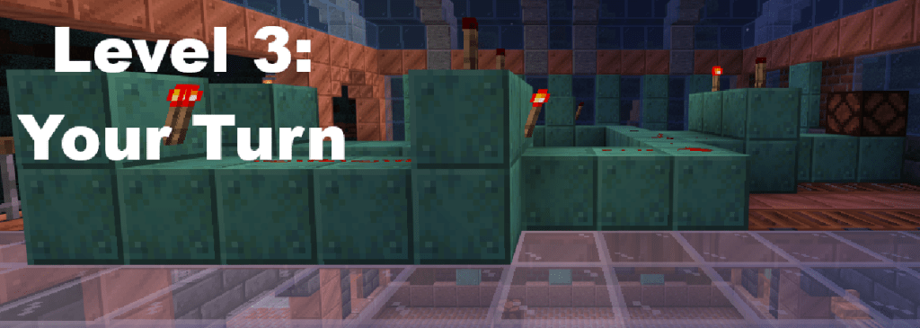
Level 3: Your Turn
Below, I have provided you with a circuit. This circuit contains the following components:
- 1 OR Gate
- 2 NOT Gates
- 3 AND Gates
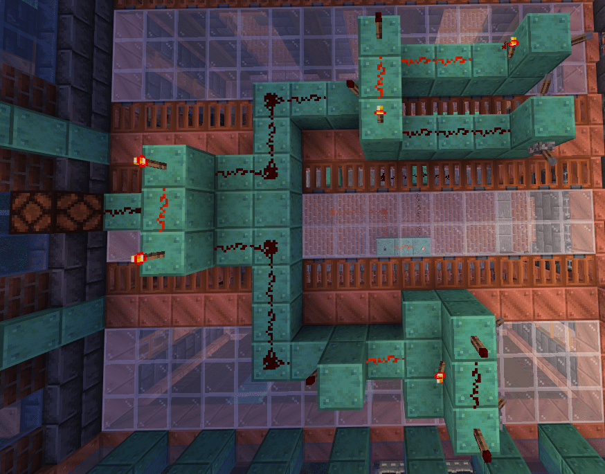
Your task is to:
- Identify the Inputs and Output(s)
- Create a diagram
- Create a truth table.
Conclusion
Minecraft, and games in general, are an amazing way to teach subjects. Truth tables and logic gates (and discrete mathematics in general) can seem tedious and boring, but once you turn these boring subjects into something fun, students are more likely to stay engaged and interested.
How do you plan on using video games for education? Let me know!


Leave a comment